|
|
|
发布时间: 2022-06-25 |
其他研究 |
|
|
|
收稿日期: 2021-04-19
基金项目: 国家自然科学基金(11804263,11747119)
中图法分类号: O43
文献标识码: A
文章编号: 2096-8299(2022)03-0307-07
|
摘要
为了研究深粗糙度随机粗糙表面的光散射现象,采用线性滤波法生成高斯分布随机粗糙表面,利用矩量法推导了深粗糙度表面的散射光平均差分散射系数。通过数值计算波长为1.064 μm的S和P线偏振入射光照射下的多组良导体表面的平均差分散射系数,发现结果出现了后向增强峰值和朗伯散射现象。根据散射宽度分布、后向增强峰值、散射峰位置等特征,分析了入射角、表面粗糙度与散射分布之间的关系。结果表明,S和P线偏振入射光良导体表面散射场能量守恒特性不同。
关键词
光散射; 粗糙表面; 矩量法; 平均差分散射系数
Abstract
To study the light scattering phenomenon of deep randomly rough surfaces, the linear filtering method is used to generate Gaussian random rough surface, and MOM is used to derive the average differential scattering coefficient of scattered light from deep roughness random rough surface.The average differential scattering coefficients of a group of good conductors irradiated by linearly polarized incident light of S and P with a wavelength of 1.064um are numerically calculated.Backward enhancement peak and Lambert scattering appear in the results.According to the scattering width distribution, backward enhancement peak and the position of the scattering peak, the relationship between incident angle and surface roughness and scattering distribution is analyzed.The energy conservation characteristics of the surface scattering field are different between S and P linearly polarized incident conductors.
Key words
light scattering; gaussian rough surface; method of moment; average differential scattering coefficient
随机粗糙表面的波散射研究始于20世纪, 英国著名物理学家RAYLEIGH L[1]研究了光垂直入射到正弦表面的散射现象; SIMONSEN I[2]研究了液体表面的光散射现象, 开创了随机粗糙表面的波散射研究领域。随后出现了许多随机粗糙表面的光散射理论研究方法, 解析方法有基尔霍夫近似法[3]、微扰法[4-5]与消光定理法。SOTO CRESPO J M等人[6]采用消光定理计算了深粗糙度表面的散射, 研究了基尔霍夫近似的有效性。ISHIMARU A等人[7]采用修正的基尔霍夫近似方法研究了深粗糙度金属和介质表面散射问题。TANG K等人[8]采用几何光学法研究了深粗糙度表面的散射特性。典型的数值方法有有限元方法[9-10]和矩量法(Method of Moment)[11-12]。SIMONSEN I等人[13]采用矩量法研究了P线偏振入射光在二维各向异性随机粗糙导体表面的光散射全角度分布特性; LETNES P A等人[14]数值计算了二维随机表面的偏振特性。
虽然随机粗糙表面散射研究的文献很多, 但是采用严格电磁场计算方法对深粗糙度表面散射的研究较少。数值方法如矩量法根据表面电流计算散射场, 不用考虑深粗糙度表面发生的多次散射现象, 计算结果精确。因此, 本文利用线性滤波法产生高斯随机粗糙表面, 采用基于矩量法的蒙特卡罗数值法计算良导体深粗糙度表面在S线偏振入射光和P线偏振入射光照射下的光散射场, 对比散射场的散射强度分布宽度、散射峰值、峰值位置等特征。
1 散射几何模型
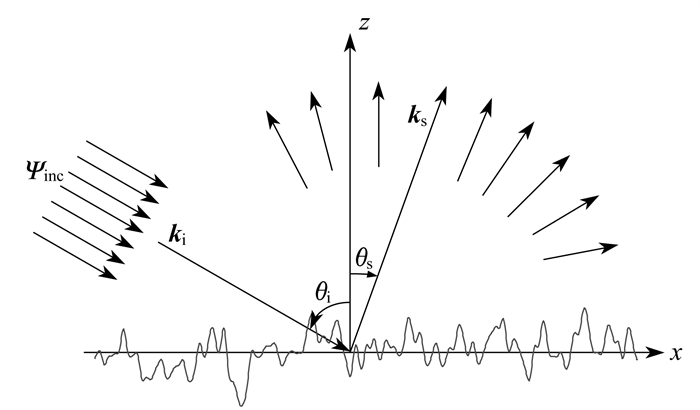
一维随机粗糙表面散射几何模型如图 1所示。
图 1中, ψinc为一维锥形入射波, θi为入射角, θS为散射角, ki为入射波波矢, kS为散射波波矢。
本文中所考虑的物理系统包含z>f(x)真空区域和z < f(x)良导体区域。假设表面起伏函数f(x)为x的单值函数, 由一个稳定的均值为零的定义为f(x)〈f(x)f(x′)〉=σ2W(|x-x′|)的高斯随机过程构成, 括号表示多个表面起伏函数实例的集平均,
| $ {{\psi }_{\text{inc}}}(r)={{\text{e}}^{\text{i}k\left( x\sin \left( {{\theta }_{\text{i}}} \right) \right)(1+\omega (r))}}\cdot {{\text{e}}^{-\frac{{{\left( x+z\tan \left( {{\theta }_{\text{i}}} \right) \right)}^{2}}}{g2}}} $ | (1) |
式中: i——虚数单位;
k——光波波数;
ω——附加相位项, ω=2(x+z tan θi)2/(kg2cos θi)2;
g——锥形宽度。
锥形宽度g决定了入射波的宽度和随机粗糙表面的尺寸。g越大, 入射波宽度就越大, 粗糙表面尺寸也越大, 计算结果更精确, 但计算强度增加, 计算时间加长, 本文中取g=L/4。
2 良导体粗糙表面光散射计算的矩量法
根据图 1中的散射结构, 对于良导体随机粗糙表面光散射, 真空区域总场等于入射场与散射场之和, 即
| $ \psi ({\mathit{\boldsymbol{r}}})={{\psi }_{\text{inc}}}({\mathit{\boldsymbol{r}}})+{{\psi }_{\text{S}}}({\mathit{\boldsymbol{r}}}) $ | (3) |
式中: ψ(r)——空间总的波函数;
r——场点位置矢量;
ψinc(r)——入射波函数;
ψS(r)——散射波函数。
利用格林函数得
| $ \left( {{\nabla }^{2}}+{{k}^{2}} \right){{g}_{1}}\left( {\mathit{\boldsymbol{r}}}, {{{\mathit{\boldsymbol{r}}}}^{\prime }} \right)=-\delta \left( {\mathit{\boldsymbol{r}}}-{{{\mathit{\boldsymbol{r}}}}^{\prime }} \right) $ | (4) |
式中: ▽——梯度算子;
r′——源点位置矢量。
式(4)中格林函数为
| $ {{g}_{1}}\left( {\mathit{\boldsymbol{r}}}, {{{\mathit{\boldsymbol{r}}}}^{\prime }} \right)=\left( \frac{\text{i}}{4} \right)H_{0}^{(1)}\left( {{k}_{1}}\left| {\mathit{\boldsymbol{r}}}-{{{\mathit{\boldsymbol{r}}}}^{\prime }} \right| \right) $ | (5) |
式中: H0(1)(·)——第一类零阶Hankel函数。
应用格林第二恒等式, 化简得到的电磁散射积分方程为
| $ \begin{align} & {{\psi }_{\text{inc}}}\left( {{{\mathit{\boldsymbol{r}}}}^{\prime }} \right)+\int\limits_{S}{{{\mathit{\boldsymbol{\hat{n}}}}}}\left[ \psi ({\mathit{\boldsymbol{r}}})\nabla g\left( {\mathit{\boldsymbol{r}}}, {{{\mathit{\boldsymbol{r}}}}^{\prime }} \right)- \right. \\ & \left. g\left( {\mathit{\boldsymbol{r}}}, {{{\mathit{\boldsymbol{r}}}}^{\prime }} \right)\nabla \psi ({\mathit{\boldsymbol{r}}}) \right]=\left\{ \begin{array}{*{35}{l}} \psi ({\mathit{\boldsymbol{r}}}), {{{\mathit{\boldsymbol{r}}}}^{\prime }}\in {{V}_{0}} \\ 0, {{{\mathit{\boldsymbol{r}}}}^{\prime }}\in {{V}_{1}} \\ \end{array} \right. \\ \end{align} $ | (6) |
式中:
V0——粗糙表面上方;
V1——粗糙表面。
对于式(6), 采用点配法[17]得到矩阵方程, 采用Bi - CGSTAB[18]算法求解矩阵方程, 得到表面场ψ(r), 进而得到散射场为
| $ \begin{align} & {{\psi }_{\text{S}}}\left( {{{\mathit{\boldsymbol{r}}}}^{\prime }} \right)=\frac{\text{i}}{4}\sqrt{\frac{2}{k\pi {{{\mathit{\boldsymbol{r}}}}^{\prime }}}}\exp \left( -\text{i}\frac{\pi }{4} \right)\cdot \\ & \ \ \ \ \ \ \ \ \ \ \ \ \exp \left( \text{i}k{{{\mathit{\boldsymbol{r}}}}^{\prime }} \right)\psi _{\text{S}}^{(N)}\left( {{\theta }_{\text{S}}} \right) \\ \end{align} $ | (7) |
| $ \begin{align} & \psi _{\text{S}}^{\prime }\left( {{\theta }_{\text{S}}} \right)= \\ & \int_{-\infty }^{\infty }{\left[ -U(x)+\psi (x)ik\left( \frac{\text{d}f}{~\text{d}x}\sin {{\theta }_{\text{S}}}-\cos {{\theta }_{\text{S}}} \right) \right]}\cdot \\ & \exp \left( -\text{i}k\left( \sin {{\theta }_{\text{S}}}x+\cos {{\theta }_{\text{S}}}z \right) \right) \\ \end{align} $ | (8) |
其中, 基函数
差分散射系数(Differential Reflection Coefficient, DRC), CDR(θS)定义为从散射方向为θS在dθS角度范围内的散射光功率PS与入射光总功率Pi的比值, 满足
| $ \frac{{{P}_{\text{S}}}}{{{P}_{\text{i}}}}=\int_{-\frac{\pi }{2}}^{\frac{\pi }{2}}{{{C}_{\text{DR}}}}\left( {{\theta }_{\text{S}}} \right)\text{d}{{\theta }_{\text{S}}} $ | (9) |
| $ {{P}_{\text{S}}}=\int_{-\frac{\text{ }\pi\text{ }}{\text{2}}}^{\frac{\pi}{2}}{\left[ \frac{{{\left| \psi _{\text{S}}^{\prime }\left( {{\theta }_{\text{S}}} \right) \right|}^{2}}}{2\eta \cdot 8\pi k} \right]}\text{d}{{\theta }_{\text{S}}} $ | (10) |
式中: η——自由空间波阻抗。
| $ {{P}_{\text{i}}}=\cos {{\theta }_{\text{i}}}\cdot g\sqrt{\frac{\pi }{2}}\frac{\frac{1-\left( 1+2{{\tan }^{2}}{{\theta }_{\text{i}}} \right)}{\left( 2{{k}^{2}}{{g}^{2}}\cos {{\theta }_{\text{i}}} \right)}}{2\eta } $ | (11) |
可得到
| $ \begin{align} & {{C}_{\text{DR}}}\left( {{\theta }_{\text{S}}} \right)= \\ & \frac{{{\left| \psi _{\text{S}}^{\prime }\left( {{\theta }_{\text{S}}} \right) \right|}^{2}}}{8\pi kg\sqrt{\frac{\pi }{2}}\cos {{\theta }_{\text{i}}}\left[ \frac{1-\left( 1+2{{\tan }^{2}}{{\theta }_{\text{i}}} \right)}{{{\left( 2{{k}^{2}}{{g}^{2}}\cos {{\theta }_{\text{i}}} \right)}^{2}}} \right]} \\ \end{align} $ | (12) |
平均差分散射系数(Mean Differential Reflection Coefficient, , MDRC)CMDR(θS)为同一粗糙度参数下多个表面散射差分散射系数的平均值
| $ \begin{align} & {{C}_{\text{MDR}}}\left( {{\theta }_{\text{S}}} \right)= \\ & \frac{\left\langle {{\left| \psi _{\text{S}}^{\prime }\left( {{\theta }_{\text{S}}} \right) \right|}^{2}} \right\rangle }{8\pi kg\sqrt{\frac{\pi }{2}}\cos {{\theta }_{\text{i}}}\left[ \frac{1-\left( 1+2{{\tan }^{2}}{{\theta }_{\text{i}}} \right)}{{{\left( 2{{k}^{2}}{{g}^{2}}\cos {{\theta }_{\text{i}}} \right)}^{2}}} \right]} \\ \end{align} $ | (13) |
记能量守恒判据
3 结果与讨论
本文数值计算采用的计算机参数如下: CPU为Intel i5-3570处理器, 频率为3.4 GHz, 内存16 G, 操作系统为Windows 7, 软件开发环境为Microsoft Visual Studio 2008, 采用Intel Visual Fortran 11编译器。光散射数值计算选择近红外波长λ=1.064 μm的S和P两种线偏振入射光; 生成不同粗糙度参数的表面, 粗糙度参数如表 1所示。表面长度为100λ, 每个参数的计算分别产生10 000个样本表面, 数值计算采样点数为N=2 048。
表 1
粗糙表面样本粗糙度参数
| 表面 | δ | T |
| 1 | 0.1λ | 0.2λ |
| 2 | 0.2λ | 0.2λ |
| 3 | 0.1λ | 1.8λ |
| 4 | 0.5λ | 1.8λ |
| 5 | 1.0λ | 1.8λ |
| 6 | 0.5λ | 0.5λ |
| 7 | 1.0λ | 1.0λ |
| 8 | 1.4λ | 2.0λ |
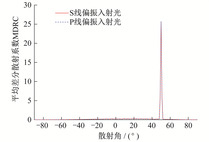
对多个粗糙度参数的表面进行数值计算发现, 在相关长度T和均方根高度δ取值较小时, S与P线偏振入射光的散射结果比较接近。当δ=0.1λ, T=0.2λ, θi=50°时, 随机表面散射强度分布中S和P线偏振入射光都有很强的镜像峰值, 二者具有相似的散射分布, 具体如图 2所示。
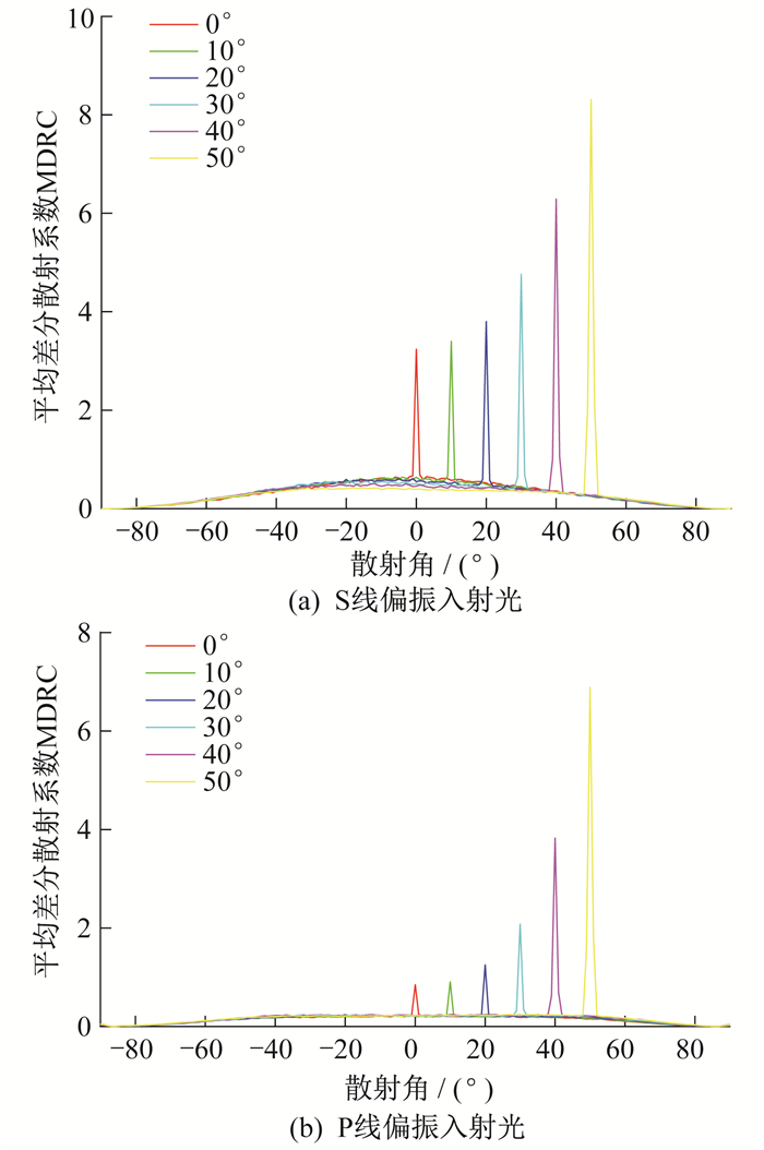
当相关长度T不变, 均方根高度δ增大时, S与P线偏振入射光的散射分布差距也变大, 当δ=0.2λ, T=0.2λ时, 随机表面散射强度分布, S和P线偏振入射光都有很强的镜像峰值, 但S线偏振入射光散射光强度高于P线偏振入射光, 尤其是S线偏振入射光散射峰值明显大于P线偏振入射光散射峰值。随着入射角增大, S和P线偏振入射光散射镜像峰值变大, 具体如图 3所示。
当δ=0.1λ, T=1.8λ时, 出现镜像散射峰, S与P线偏振入射光散射分布相似, 镜像峰值随着入射角的增大而增大; 随着δ的增大, 散射强度分布变宽, 出现类似朗伯体漫反射现象, 散射强度分很宽, 因此在T固定时, δ会有一个朗伯散射区间出现, 具体如图 4所示。
当δ=0.5λ, T=1.8λ在入射角θi < 20°时出现朗伯散射; 随着入射角度的增大, 散射强度增大, 但增幅不大, 并且散射峰值向大散射角方向移动; 随着δ的进一步增大, 出现后向增强峰值, 具体如图 5所示。
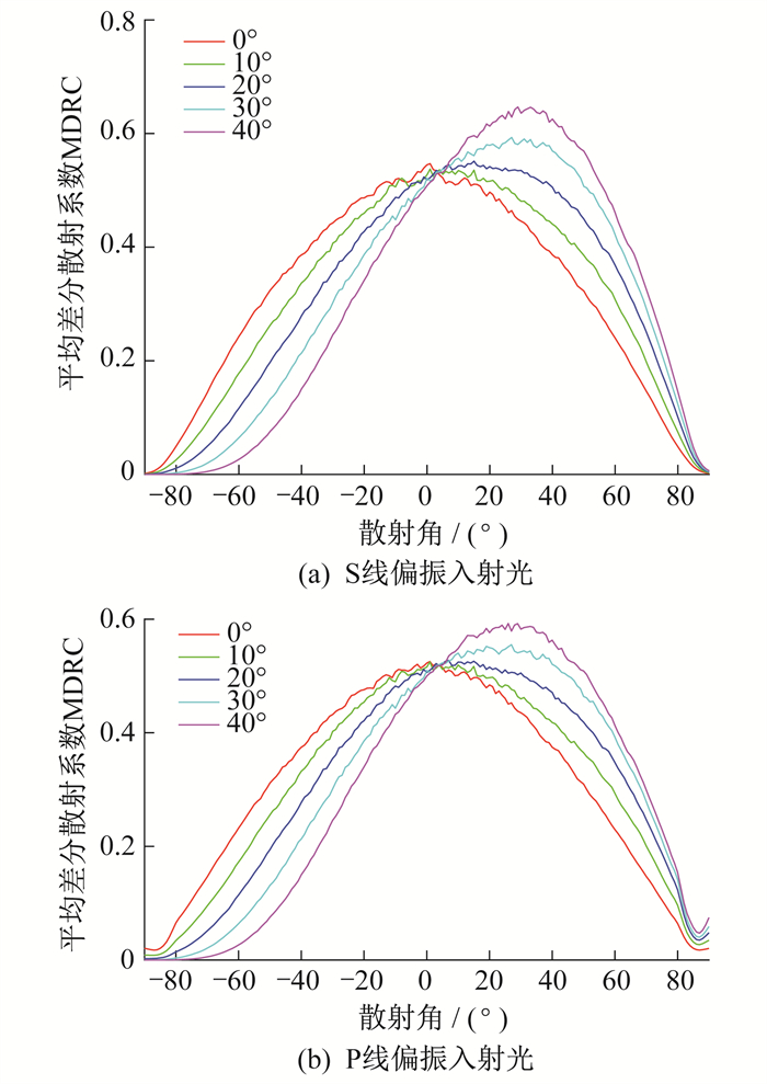
当δ=1.0λ, T=1.8λ时的随机表面散光MDRC分布如图 6所示。入射角θi为0°, 10°, 20°时在朗伯散射分布中出现后向增强峰值。
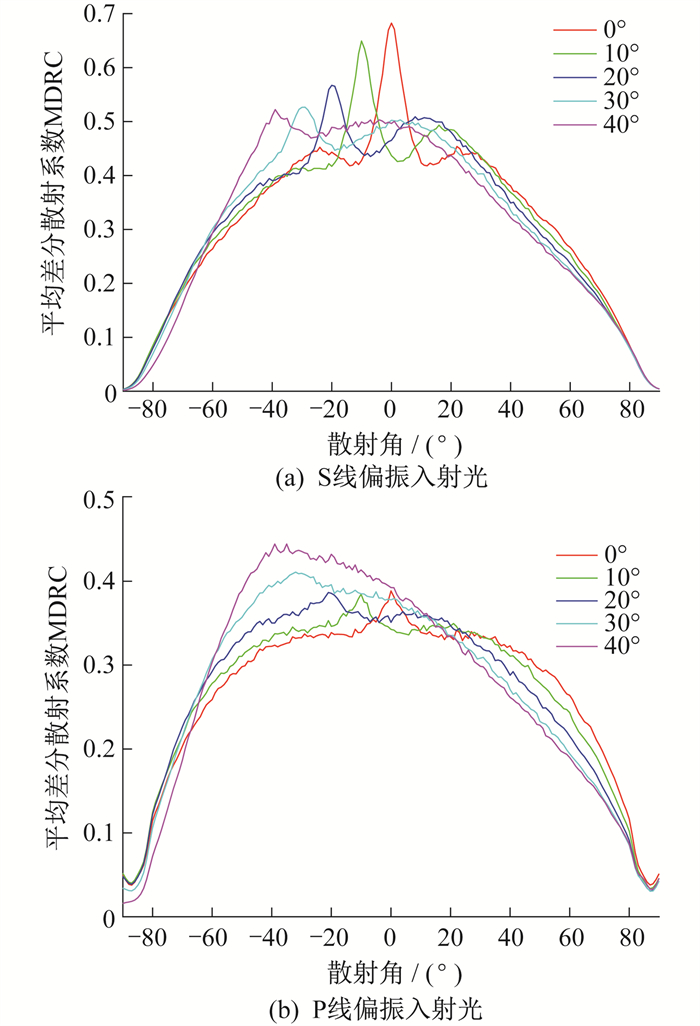
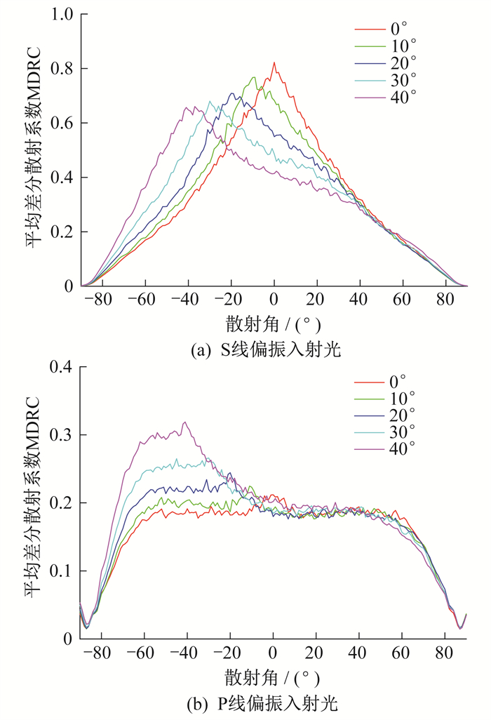
当δ=0.5λ, T=0.5λ和δ=1.0λ, T=1.0λ时的随机表面散光MDRC分布如图 7和图 8所示。
当θi < 20°, δ/T不变, 峰值随着δ或T的增大而增大, 增幅不大, 当θi>20°, δ/T不变, 峰值随着δ或T的增大而减小, 增幅不大。
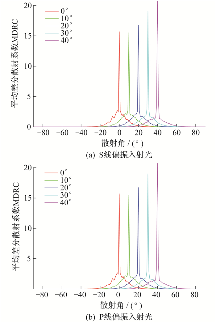
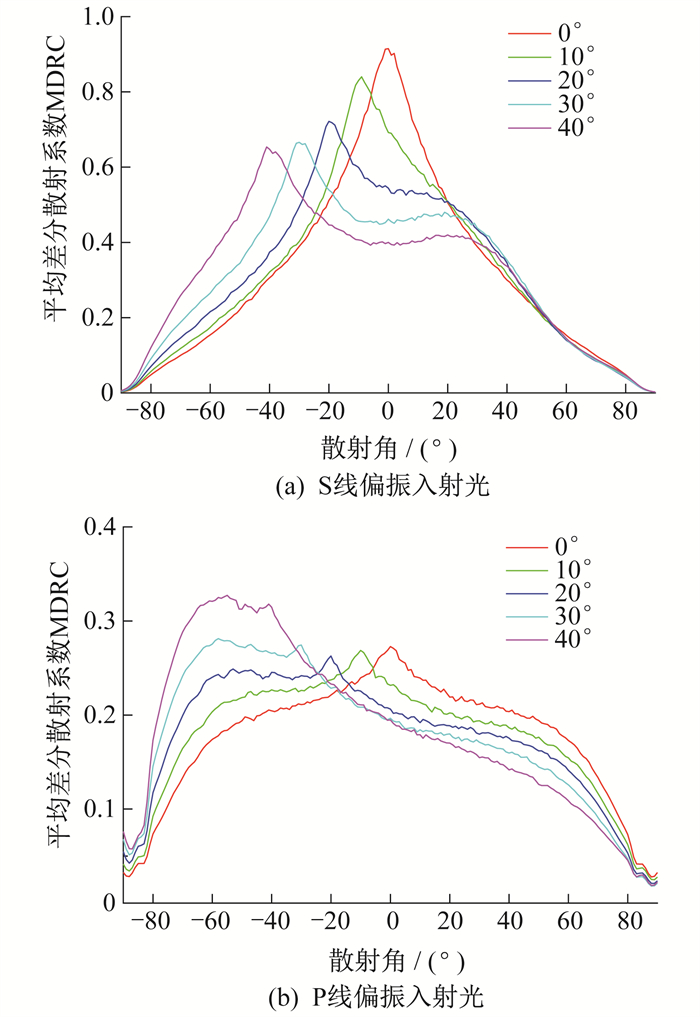
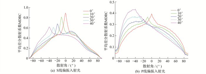
增强的后向散射峰值在入射角θi≤20°时比较明显, 后向峰值随着入射角增大而减小。当δ=1.4λ, T=2.0λ, θi=0°时, 中间有后向增强峰, 但S线偏振入射光的后向峰值要大于P线偏振入射光的后向峰值; 随着入射角的增大, P线偏振入射光散射分布朝后向方向倾斜, 而S线偏振入射光散射分布则朝前向方向倾斜, 具体如图 9所示。
针对以上计算结果计算能量守恒判据u(θi), 具体如表 2所示, 其中入射角度为0°~40°。
表 2
能量守恒判据u(θi)
| δ | T | S线偏振入射光入射角 | P线偏振入射光入射角 | |||||||||
| 0° | 10° | 20° | 30° | 40° | 0° | 10° | 20° | 30° | 40° | |||
| 0.2λ | 0.2λ | 1.010 | 1.010 | 1.010 | 1.000 | 1.000 | 0.443 | 0.451 | 0.480 | 0.521 | 0.589 | |
| 0.1λ | 1.8λ | 1.040 | 1.030 | 1.020 | 1.020 | 1.010 | 1.030 | 1.030 | 1.020 | 1.010 | 1.010 | |
| 0.5λ | 1.8λ | 0.999 | 0.999 | 0.999 | 0.999 | 0.999 | 0.979 | 0.939 | 0.969 | 0.956 | 0.977 | |
| 1.0λ | 1.8λ | 0.999 | 0.999 | 0.999 | 0.999 | 0.999 | 0.841 | 0.843 | 0.847 | 0.856 | 0.868 | |
| 0.5λ | 0.5λ | 0.999 | 0.999 | 0.998 | 0.999 | 0.999 | 0.496 | 0.506 | 0.529 | 0.560 | 0.598 | |
| 1.0λ | 1.0λ | 0.999 | 0.999 | 0.999 | 0.999 | 0.998 | 0.556 | 0.556 | 0.557 | 0.564 | 0.584 | |
| 1.4λ | 2.0λ | 0.999 | 0.999 | 0.999 | 0.999 | 0.999 | 0.724 | 0.718 | 0.715 | 0.727 | 0.756 | |
对于良导体粗糙表面来说, 粗糙面上所有入射光能量求转化为散射光能量。因此
| $ u\left( {{\theta }_{\text{i}}} \right)=\int{\left\langle {{C}_{\text{MDR}}}\left( {{\theta }_{\text{S}}} \right) \right\rangle }\text{d}{{\theta }_{\text{S}}}=1 $ | (21) |
从表 2可以看到, S线偏振入射光在不同入射角, 不同粗糙度参数下的散射都满足能量守恒条件, 而P线偏振入射光则不能满足能量守恒条件。这种差异可由表面等离子体激元(SPP)来解释[19-21]。根据文献[2]中的计算, S线偏振入射光在表面散射时不会产生SPP, 而P线偏振入射光在表面散射时会产生SPP, 导致P线偏振入射光部分能量转化为SPP能量, 因此出现了散射总能量小于入射能量的现象; 而S线偏振入射光能量与入射光能量相同。从表3中可以看到: 对于P线偏振入射光, δ/T越小, 表面斜率越小, 散射能量越多, 产生的SPP越小; 当δ/T相同时, δ或T越大, 散射能量越大, 产生的SPP越小。
4 结语
利用线性滤波法产生高斯随机粗糙表面, 采用矩量法计算了大量不同粗糙度的良导体表面在S和P线偏振入射光入射下的散射光MDRC, 数值计算结果如下。
(1) 当均方根高度与相关长度较小时, S和P线偏振入射光散射分布相似, 具有很强的镜像峰值, 峰值随入射角增大而增大。
(2) 当相关长度T不变时, δ增大, 有一个区域会出现朗伯漫散射, 入射角一般在θi < 20°, 散射角保持在一个很宽的散射分布, 随着入射角增大而变窄。
(3) 较大的均方根高度表面散射时有后向增强散射峰, 峰值随着δ/T增大而增大, 后向散射峰在20°最强, 随着角度增大而减小。当θi < 20°, δ/T不变时, 峰值随着δ或T的增大而增大。增幅不大, 当θi>20°, δ/T不变时, 峰值随着δ或T的增大而减小, 增幅不大。
(4) S线偏振入射光的散射场基本保持与入射场能量守恒, 而P线偏振入射光在良导体表面产生SPP, 因此其散射场能量小于入射场能量。δ/T越小, 散射能量越多; 当δ/T相同时, δ或T越大, 散射能量越大。
参考文献
-
[1]RAYLEIGH L. On the dynamical theory of gratings[J]. Proceedings of the Royal Society of London.Series A, 1907, 79: 399-416.
-
[2]SIMONSEN I. Optics of surface disordered systems[J]. The European Physical Journal Special Topics, 2010, 181(1): 100-103.
-
[3]WIRGIN A. Scattering from sinusoidal gratings: an evaluation of the Kirchhoff approximation[J]. Journal of the Optical Society of America, 1983, 73(8): 1028-1041. DOI:10.1364/JOSA.73.001028
-
[4]OGILVY J A, MERKLINGER H M. Theory of wave scattering from random rough surfaces[J]. The Journal of the Acoustical Society of America, 1991, 90(6): 3382-3382.
-
[5]LU J Q, GU Z H, MENDEZ E R, et al. Scattering of light from a rough dielectric film on a reflecting substrate: diffuse fringes[J]. Journal of the Optical Society of America, 1998, 15(1): 185-195. DOI:10.1364/JOSAA.15.000185
-
[6]SOTO CRESPO J M, NIETO VESPERINAS M. Electromagnetic scattering from very rough random surfaces and deep re flection gratings[J]. Journal of the Optical Society of America, 1989, 6(3): 367-384. DOI:10.1364/JOSAA.6.000367
-
[7]ISHIMARU A, CHEN J S. Scattering from very rough metallic and dielectric surfaces: a theory based on the modified Kirchhoff approximation[J]. Waves in Random Media, 1991, 1(1): 21-34. DOI:10.1088/0959-7174/1/1/003
-
[8]TANG K, DIMENNA R A, BUCKIUS R O. Regions of validity of the geometric optics approximation for angular scattering from very rough surfaces[J]. International Journal of Heat and Mass Transfer, 1996, 40(1): 49-59. DOI:10.1016/S0017-9310(96)00073-7
-
[9]SELLGREN U, BJORKLUND S, ANDERSSON S. A finite element-based model of normal contact between rough surfaces[J]. Wear, 2003, 254(11): 1180-1188. DOI:10.1016/S0043-1648(03)00332-6
-
[10]HYUN S, PEI L, ROBBINS M, et al. Finite-element analysis of contact between elastic self-affine surfaces[J]. Physical Review E, 2004, 70(2): 026117. DOI:10.1103/PhysRevE.70.026117
-
[11]PAK K, JOHNSON J, TSANG L, et al. Backscattering enhancement of electromagnetic waves from two-dimensional perfectly conducting random rough surfaces based on Monte Carlo simulations[J]. Journal of the Optical Society of America, 1995, 12(11): 2491-2499. DOI:10.1364/JOSAA.12.002491
-
[12]PAK K, TSANG L, JOHNSON J. Numerical simulations and backscattering enhancement of electromagnetic waves from two-dimensional dielectric random rough surfaces with the sparse-matrix canonical grid method[J]. Journal of the Optical Society of America, Part A: Optics and Image Science, 1997, 14(7): 1515-1529. DOI:10.1364/JOSAA.14.001515
-
[13]SIMONSEN I, MARADUDIN A A, LESKOVA T A. Scattering of electromagnetic waves from two-dimensional randomly rough perfectly conducting surfaces: the full angular intensity distribution[J]. Physical Review A, 2010, 81(1): 013806. DOI:10.1103/PhysRevA.81.013806
-
[14]LETNES P A, MARADUDIN A A, NORDAM T, et al. Calculation of the Mueller matrix for scattering of light from two-dimensional rough surfaces[J]. Physical Review A, 2012, 86(3): 031803. DOI:10.1103/PhysRevA.86.031803
-
[15]HU Y Z, TONDER K. Simulation of 3-D random rough surface by 2-D digital filter and fourier analysis[J]. International Journal of Machine Tools and Manufacture, 1992, 32(1/2): 83-90.
-
[16]PATIR N. A numerical procedure for random generation of rough surfaces[J]. Wear, 1978, 47(2): 263-277. DOI:10.1016/0043-1648(78)90157-6
-
[17]HARRINGTON R F, HARRINGTON J L. Field computation by moment methods[M]. Oxford: Oxford University Press, 1996: 1-3.
-
[18]VORST H. Bi-CGSTAB: a fast and smoothly converging variant of Bi-CG for the solution of nonsymmetric linear systems[J]. SIAM Journal on scientific and Statistical Computing, 1992, 13(2): 631-644. DOI:10.1137/0913035
-
[19]TILLEY D R. Surface polaritons: electromagnetic waves at surfaces and interfaces[J]. Journal of Modern Optics, 1983, 30(11): 1501-1501.
-
[20]ZAYATS A V, SMOLYANINOV I I, MARADUDIN A A. Nano-optics of surface plasmon polaritons[J]. Physics reports, 2005, 408(3): 131-314.
-
[21]KIK P G, BRONGERSMA M L. Surface plasmon nanophotonics, in surface plasmon nanophotonics[C]//International Conference on Physical. Berlin: Springer, 2007: 1-9.


