|
|
|
发布时间: 2022-02-28 |
清洁安全发电 |
|
|
|
收稿日期: 2020-03-24
中图法分类号: TM341;TM351
文献标识码: A
文章编号: 2096-8299(2022)01-0017-05
|
摘要
传统的永磁同步电机(PMSM)无传感器驱动控制技术在低转速时, 由于反电动势幅值低, 所以存在转子角度误差大, 抖振现象严重等问题。为在各类PMSM的运行工况中均能得到转子的位置信息, 详尽分析了PMSM的数学模型, 提出了一种脉振高频电压信号注入策略。通过在估计的直轴中注入高频电压激励, 以构建交直轴电感差异的凸极效应, 通过检测交轴的高频电流响应以提取出转子误差信息, 实现了转子位置的实时追踪。理论分析和仿真结果均表明, 该策略能够准确辨识永磁转子的实时角度位置, 适用于PMSM的各类工况, 在瞬时增减负载时, 表现出较强的鲁棒性。
关键词
永磁同步电机; 脉振高频注入; 凸极效应
Abstract
Aiming at the problems of the traditional sensorless drive control technology of permanent magnet synchronous motors(PMSM) at low speeds due to the low back-EMF amplitude, the large rotor angle error, and the severe chattering phenomenon, in order to obtain the rotor position information in all kinds of PMSM working conditions, the mathematical model of PMSM is analyzed in detail, and a high-frequency pulse vibration voltage signal injection strategy is studied.By injecting high-frequency voltage excitation into the estimated straight axis, the salient pole effect of the difference in inductance between the orthogonal axis and the orthogonal axis is constructed.By detecting the high-frequency current response of the orthogonal axis to extract the rotor error information, real-time tracking of the rotor position is achieved.Theoretical analysis and simulation results show that the strategy can accurately identify the real-time angular position of the permanent magnet rotor, and is suitable for various working conditions of permanent magnet synchronous motors.It shows strong robustness when the load is momentarily increased or decreased.
Key words
permanent magnet synchronous motor; high frequency injection of pulse vibration; salient pole effect
永磁同步电机(Permanent Magnet Synchronous Motor, PMSM)具有功率密度高、维护成本低、转矩脉动更小的正弦波反电动势等优点, 正逐步成为工业应用的主力[1-3]。为实现PMSM的精确转速控制, 必须实时获取永磁转子的位置信息, 而使用转子码盘不仅会增加安装和维护成本, 同时也会降低电机驱动系统的稳定性, 所以研究实现PMSM的无转子位置传感器驱动控制技术具有重要的经济意义和实用价值[4]。
许多学者对PMSM无传感器驱动技术进行了研究和分析, 提出了多种控制策略, 按理论基础总体可分为2类, 即基于电机动态模型和基于电机凸极特性[5]。电机动态模型的构建需要测量电机的反电动势, 故电机需运行在中高速工况下[4-5]。文献[6]使用滑模观测器重构解算出转子的实时位置, 但在低速运行时反电动势幅值较小, 转子位置误差较大, 抖振现象严重。为使在零低速时也能得到转子位置信息, 可利用PMSM的凸极特性。文献[7-8]分析了旋转高频信号注入策略, 适用于凸极转子结构的内嵌式永磁电机(IPMSM), 但不适用于表贴式永磁电机(SPMSM)。
为在各类PMSM的运行工况中均能得到转子的位置信息, 本文详尽分析了PMSM的数学模型, 提出了一种脉振高频电压信号注入策略, 通过构建PMSM的凸极特性以适用于SPMSM。
1 PMSM数学模型及矢量控制理论
1.1 PMSM数学模型
首先做如下假设: 电机电枢绕组呈三相对称分布, 且均为零阻尼绕组; 永磁转子磁场以正弦分布; 不计电机运行中的涡流和相关磁滞损耗; 忽略电机铁心饱和, 电感参数不变。
PMSM的定子电流和永磁转子共同组成定子磁链, 且与转子的位置相关。磁链方程[9]可表示为
| $ \left[\begin{array}{c} \psi_{\mathrm{a}} \\ \psi_{\mathrm{b}} \\ \psi_{\mathrm{c}} \end{array}\right]=\left[\begin{array}{ccc} L_{\mathrm{a}} & M_{\mathrm{ab}} & M_{\mathrm{ac}} \\ M_{\mathrm{ab}} & L_{\mathrm{b}} & M_{\mathrm{bc}} \\ M_{\mathrm{ac}} & M_{\mathrm{bc}} & L_{\mathrm{c}} \end{array}\right]\left[\begin{array}{c} i_{\mathrm{a}} \\ i_{\mathrm{b}} \\ i_{\mathrm{c}} \end{array}\right]+\psi_{\mathrm{f}}\left[\begin{array}{c} \cos \theta \\ \cos \left(\theta-\frac{2 {\rm{ \mathit{ π} }}}{3}\right) \\ \cos \left(\theta-\frac{4 {\rm{ \mathit{ π} }}}{3}\right) \end{array}\right] $ | (1) |
式中: ψa, ψb, ψc——三相电枢绕组磁链;
La, Lb, Lc——电枢绕组自感;
Mab, Mac, Mbc——电枢绕组互感;
ia, ib, ic——电枢绕组相电流;
ψf——永磁转子的磁链;
θ——永磁转子的角度位置。
SPMSM气隙均匀, 三相绕组的自感和互感分布均匀, 与转子的角度位置无关, 均为常数。故有下式成立
| $ M_{\mathrm{ab}}=M_{\mathrm{ac}}=M_{\mathrm{bc}} $ | (2) |
| $ L_{\mathrm{a}}=L_{\mathrm{b}}=L_{\mathrm{c}} $ | (3) |
电枢绕组的电压方程为
| $ \left\{\begin{array}{l} u_{\mathrm{a}}=R_{\mathrm{a}} i_{\mathrm{a}}+\frac{\mathrm{d} \psi_{\mathrm{a}}}{\mathrm{d} t} \\ u_{\mathrm{b}}=R_{\mathrm{b}} i_{\mathrm{b}}+\frac{\mathrm{d} \psi_{\mathrm{b}}}{\mathrm{d} t} \\ u_{\mathrm{c}}=R_{\mathrm{c}} i_{\mathrm{c}}+\frac{\mathrm{d} \psi_{\mathrm{c}}}{\mathrm{d} t} \end{array}\right. $ | (4) |
式中: ua, ub, uc——三相电枢绕组的相电压;
Ra, Rb, Rc——电枢电阻, 且Ra=Rb=Rc。
以上磁链方程和电压方程在dq旋转坐标系下可分别[10]表示为
| $ \left[\begin{array}{c} \psi_{d} \\ \psi_{q} \\ \psi_{0} \end{array}\right]=\left[\begin{array}{ccc} L_{d} & 0 & 0 \\ 0 & L_{q} & 0 \\ 0 & 0 & L_{0} \end{array}\right]\left[\begin{array}{c} i_{d} \\ i_{q} \\ i_{0} \end{array}\right]+\left[\begin{array}{c} \psi_{\mathrm{f}} \\ 0 \\ 0 \end{array}\right] $ | (5) |
| $ \left\{\begin{array}{l} u_{d}=R i_{d}+\frac{\mathrm{d} \psi_{d}}{\mathrm{~d} t}-\omega \psi_{q} \\ u_{q}=R i_{q}+\frac{\mathrm{d} \psi_{q}}{\mathrm{~d} t}+\omega \psi_{d} \\ u_{0}=R i_{0}+\frac{\mathrm{d} \psi_{0}}{\mathrm{~d} t} \end{array}\right. $ | (6) |
式中: ψd, ψq——d轴和q轴磁链;
Ld, Lq——d轴和q轴电感;
id, iq——d轴和q轴电流;
ud, uq——d轴和q轴电压;
R——相电枢电阻;
ω——永磁转子角速度。
零序电压u0、零序电流i0、零序磁链ψ0的计算公式分别为
| $ \left\{\begin{array}{l} u_{0}=\frac{u_{\mathrm{a}}+u_{\mathrm{b}}+u_{\mathrm{c}}}{3} \\ i_{0}=\frac{i_{\mathrm{a}}+i_{\mathrm{b}}+i_{\mathrm{c}}}{3} \\ \psi_{0}=\frac{\psi_{\mathrm{a}}+\psi_{\mathrm{b}}+\psi_{\mathrm{c}}}{3} \end{array}\right. $ | (7) |
对于SPMSM, 由于其为隐极式永磁机, 因此如下公式成立
| $ L_{d}=L_{q} $ | (8) |
转矩方程为
| $ \begin{aligned} T_{e}=& p_{n}\left(\psi_{d} i_{q}-\psi_{q} i_{d}\right)=\\ & p_{n}\left[\psi_{\mathrm{f}} i_{q}+\left(L_{d}-L_{q}\right) i_{d} i_{q}\right] \end{aligned} $ | (9) |
式中: pn——PMSM的极对数。
转矩由定子磁场和永磁转子磁场所产生的主电磁转矩和由交直轴电感不等所组成的磁阻转矩组成。
1.2 PMSM矢量控制理论
矢量控制即永磁转子的磁场定向控制。设定永磁转子磁场N极所指方向为直轴即d轴, 以正向旋转方向超前直轴90°的轴线为交轴即q轴。通过对PMSM交直轴电流分量iq和id的调节即可实现对定子转矩和转子磁通解耦控制, 即对三相电流矢量的控制。
根据对id和iq控制方式的不同, PMSM的电流矢量控制策略主要可分为以下几类: 直轴电流为零控制, 即id恒为零, 是矢量控制中较为简单的电流控制策略, 仅对交轴分量的调节不会导致永磁转子退磁, 故应用较为广泛[11-12]; 在大功率PMSM驱动场合通常使用恒定磁链控制和单位功率因数控制[13-14]; 转矩电流比最大是指在输出相同的电磁转矩时, 使得三相电流矢量的幅值尽可能小, 该方法能够减小驱动器损耗和最大限度地利用已有的逆变器容量。本文以小功率SPMSM作为研究对象, 故采用id=0的控制策略。
2 脉振高频注入法理论分析
2.1 PMSM高频电信号模型
当三相电源完全对称时, 式(6)可简化为
| $ \left\{\begin{array}{l} u_{d}=R i_{d}+\frac{\mathrm{d} \psi_{d}}{\mathrm{~d} t}-\omega \psi_{q} \\ u_{q}=R i_{q}+\frac{\mathrm{d} \psi_{q}}{\mathrm{~d} t}+\omega \psi_{d} \end{array}\right. $ | (10) |
当电压激励信号ud和uq中包含基频转速和高频注入分量时, 根据线性系统的叠加定理, 可拆解为2个频率旋转坐标系下的d轴和q轴分量, 公式为
| $ \left\{\begin{array}{l} u_{d \mathrm{b}}=R i_{d \mathrm{b}}+\frac{\mathrm{d} \psi_{d \mathrm{b}}}{\mathrm{d} t}-\omega \psi_{q \mathrm{b}} \\ u_{q \mathrm{b}}=R i_{q \mathrm{b}}+\frac{\mathrm{d} \psi_{q \mathrm{b}}}{\mathrm{d} t}+\omega \psi_{d \mathrm{b}} \end{array}\right. $ | (11) |
| $ \left\{\begin{array}{l} u_{d \mathrm{h}}=R i_{d \mathrm{h}}+\frac{\mathrm{d} \psi_{d \mathrm{h}}}{\mathrm{d} t}-\omega \psi_{q \mathrm{h}} \\ u_{q \mathrm{h}}=R i_{q \mathrm{h}}+\frac{\mathrm{d} \psi_{q \mathrm{h}}}{\mathrm{d} t}+\omega \psi_{d \mathrm{h}} \end{array}\right. $ | (12) |
式中: udb, uqb——基频电压激励d轴和q轴分量;
udh, uqh——高频电压激励d轴和q轴分量;
idb, iqb——基频电流响应d轴和q轴分量;
idh, iqh——高频电流响应d轴和q轴分量;
ψdb, ψqb——基频磁链d轴和q轴分量;
ψdh, ψqh——高频磁链d轴和q轴分量。
又因ψdh和ψqh仅来自于idh和iqh, 与永磁转子无关, 故
| $ \left\{\begin{array}{l} u_{d \mathrm{h}}=R i_{d \mathrm{h}}+L_{d} \frac{\mathrm{d} i_{d \mathrm{h}}}{\mathrm{d} t}-\omega L_{q} i_{q \mathrm{h}} \\ u_{q \mathrm{h}}=R i_{q \mathrm{h}}+L_{q} \frac{\mathrm{d} i_{q \mathrm{h}}}{\mathrm{d} t}+\omega L_{d} i_{d \mathrm{h}} \end{array}\right. $ | (13) |
当idh和iqh分量的角频率ωh较高时, 式(13)可简化为高频分量导数项, 写成复频域量形式为
| $ \left\{\begin{array}{l} \dot{U}_{d \mathrm{h}}=\mathrm{j} \omega_{\mathrm{h}} L_{d} \dot{I}_{d \mathrm{h}}=Z_{d \mathrm{h}} \dot{I}_{d \mathrm{h}} \\ \dot{U}_{q \mathrm{h}}=\mathrm{j} \omega_{\mathrm{h}} L_{q} \dot{I}_{q \mathrm{h}}=Z_{q \mathrm{h}} \dot{I}_{q \mathrm{h}} \end{array}\right. $ | (14) |
式中:
Zdh, Zqh——高频阻抗d轴和q轴分量。
式(14)即为PMSM高频电信号模型。
2.2 脉振高频信号注入法原理
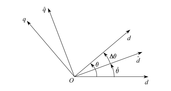
假设当前转子实际角度位置为θ, 估计角度为
由坐标旋转变换, 两坐标系之间的转换关系为
| $ \left[\begin{array}{c} \dot{U}_{d \mathrm{h}} \\ \dot{U}_{q \mathrm{h}} \end{array}\right]=\left[\begin{array}{cc} \cos \Delta \theta & \sin \Delta \theta \\ -\sin \Delta \theta & \cos \Delta \theta \end{array}\right]\left[\begin{array}{c} \dot{U}_{d \mathrm{h}}^{\prime} \\ \dot{U}_{q \mathrm{h}}^{\prime} \end{array}\right] $ | (15) |
| $ \left[\begin{array}{l} \dot{I}_{d \mathrm{h}} \\ \dot{I}_{q \mathrm{h}} \end{array}\right]=\left[\begin{array}{cc} \cos \Delta \theta & \sin \Delta \theta \\ -\sin \Delta \theta & \cos \Delta \theta \end{array}\right]\left[\begin{array}{l} \dot{I}_{d \mathrm{h}}^{\prime} \\ \dot{I}_{q \mathrm{h}}^{\prime} \end{array}\right] $ | (16) |
式中:
由式(14)可得
| $ \left[\begin{array}{l} \dot{I}_{d \mathrm{h}} \\ \dot{I}_{q \mathrm{h}} \end{array}\right]=\left[\begin{array}{cc} Y_{d \mathrm{h}} & 0 \\ 0 & Y_{q \mathrm{h}} \end{array}\right]\left[\begin{array}{l} \dot{U}_{d \mathrm{h}} \\ \dot{U}_{q \mathrm{h}} \end{array}\right] $ | (17) |
式中: Ydh, Yqh——高频导纳d轴和q轴分量, 且
| $ {Y_{d{\rm{h}}}} = Z_{d{\rm{h}}}^{ - 1},{Y_{q{\rm{h}}}} = Z_{q{\rm{h}}}^{ - 1}。$ |
将式(15)和式(16)代入式(17)中可得
| $ \left[\begin{array}{c} \dot{I}_{d \mathrm{h}}^{\prime} \\ \dot{I}_{q \mathrm{h}}^{\prime} \end{array}\right]=\left[\begin{array}{cc} Y+\frac{\Delta Y}{2} \cos (2 \Delta \theta) & \frac{\Delta Y}{2} \sin (2 \Delta \theta) \\ \frac{\Delta Y}{2} \sin (2 \Delta \theta) & Y-\frac{\Delta Y}{2} \cos (2 \Delta \theta) \end{array}\right]\left[\begin{array}{c} \dot{U}_{d \mathrm{h}}^{\prime} \\ \dot{U}_{q \mathrm{h}}^{\prime} \end{array}\right] $ | (18) |
式中: Y——平均导纳, 且Y=(Ydh+Yqh)/2;
ΔY——差分导纳, 且ΔY=Ydh-Yqh。
若在估计的
| $ \left[\begin{array}{c} \dot{I}_{d \mathrm{h}}^{\prime} \\ \dot{I}_{q \mathrm{h}}^{\prime} \end{array}\right]=\left[\begin{array}{c} Y+\frac{\Delta Y}{2} \cos (2 \Delta \theta) \\ \frac{\Delta Y}{2} \sin (2 \Delta \theta) \end{array}\right] \dot{U}_{\mathrm{h}} $ | (19) |
可知
| $ \dot{I}_{q \mathrm{h}}^{\prime}=\frac{\Delta Y}{2} \sin (2 \Delta \theta) \dot{U}_{\mathrm{h}} $ | (20) |
取
| $ \dot{I}_{q \mathrm{h}}^{\prime}=\frac{\Delta L}{2 \omega_{\mathrm{h}} L_{q} L_{d}} \sin (2 \Delta \theta) U_{\mathrm{h}} \mathrm{e}^{-\frac{i {\rm{ \mathit{ π} }}}{2}} $ | (21) |
其中ΔL=Lq-Ld, 可知通过对估计的
| $ i_{q \mathrm{h}}^{\prime}=\frac{\Delta L}{2 \omega_{\mathrm{h}} L_{q} L_{d}} \sin (2 \Delta \theta) U_{\mathrm{h}} \sin \left(\omega_{\mathrm{h}} t\right) $ | (22) |
可对i′qh做如下处理
| $ i_{q \mathrm{h}}^{\prime} \sin \left(\omega_{\mathrm{h}} t\right)=\frac{\Delta L}{2 \omega_{\mathrm{h}} L_{q} L_{d}} \sin (2 \Delta \theta) U_{\mathrm{h}} \frac{1-\cos \left(2 \omega_{\mathrm{h}} t\right)}{2} $ | (23) |
将式(23)通过低通滤波器(LPF)即可得到
| $ f(\Delta \theta)=\frac{\Delta L}{4 \omega_{\mathrm{h}} L_{q} L_{d}} \sin (2 \Delta \theta) U_{\mathrm{h}} $ | (24) |
当Δθ较小时
| $ f(\Delta \theta) \approx \frac{\Delta L}{2 \omega_{\mathrm{h}} L_{q} L_{d}} \Delta \theta U_{\mathrm{h}}=K \Delta \theta $ | (25) |
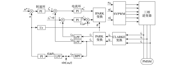
由此可求得估算角度误差的反馈项, 通过闭环调节使得f(Δθ)逼近于零, 即可实现永磁转子角度位置的实时追踪。通过脉振高频电压注入法实时求取转子位置的无位置PMSM驱动控制框图如图 2所示。其中udc为直流母线电压。
3 仿真结果分析
为了验证上述理论的正确性和本文所提策略的有效性, 基于MATLAB/Simulink搭建了PMSM无位置驱动系统进行仿真。其中, 直流母线电压为650 V, 交直轴电感Ld=Lq=3.96 mH, 电枢电阻为0.91 Ω, 极对数为2, 额定转速为3 000 r/min, 额定转矩为12 N·m。为验证中低速时脉振高频注入策略的有效性, 选择低速100 r/min和中速1 500 r/min工况进行仿真, 其中高频注入脉振电压频率为1 kHz。
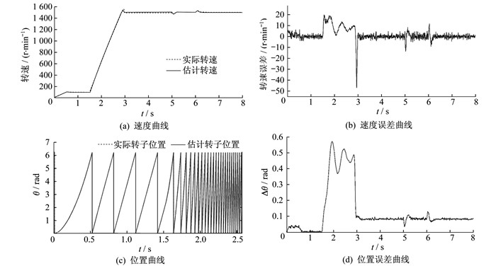
PMSM空载启动, 稳定运行在100 r/min后, 加速至1 500 r/min的仿真运行结果如图 3所示。在5 s时突增6 N·m的负载, 在6 s时突减6 N·m的负载。
由图 3可以看出: 实际转速和估计转速、实际转子位置和估计转子位置曲线几乎重合, 说明脉振高频注入算法的正确性; 在负载扰动时, 估计转速可实时追踪实际转速, 说明该系统具有强大的鲁棒性, 具有较好的静态与动态性能; 速度误差曲线在稳态时波动值小于10 r/min, 位置误差曲线在低速稳态(转速为100 r/min)时保持在零附近。在转速进一步提升时, 由于基频信号幅值进一步增加, 而控制系统中的数字滤波器和注入的脉振高频分量未进行动态调整, 故引入了0.1 rad的估算误差。
由上文的理论分析可知, 注入的脉振高频电压分量会增加逆变器调制度, 减小基波分量的有效调节范围, 同时产生的高频电流响应会进一步增加逆变器的损耗, 使得整个驱动系统效率降低。此外, 由于在实际应用中, 数字信号处理器难以实现开关周期内的高阶数字滤波器功能, 过渡带较宽, 无法有效滤除基频成分, 造成较大的转子位置估算误差, 因此当转速提升、反电动势幅值增大时, 应采用电机动态模型的方法估算转子位置, 以降低逆变器损耗, 减小转子估算误差。
4 结语
本文针对传统的高频信号注入策略在SPMSM低速运行时难以利用电机的凸极效应实现永磁转子位置的辨识, 提出了一种脉振高频电压信号注入策略, 通过构建凸极效应使其适用于各类PMSM。理论分析和仿真结果均表明, 该策略在中低速工况下动态响应速度快、稳态误差小, 具有较强的鲁棒性和实用价值。此外, 由于该策略在高速大转矩运行时会引入转子位置估算误差和增加逆变器损耗, 因此接下来的研究方向可侧重于如何设计性能更优的PMSM无位置传感器混合控制策略。
参考文献
-
[1]王永晴, 雷景生, 刘大明. 基于磁链估计的PMSM无传感器矢量控制[J]. 上海电力学院学报, 2016, 32(2): 175-180. DOI:10.3969/j.issn.1006-4729.2016.02.014
-
[2]MOUJAHED M, BENAZZA H, JEMLI M, et al. Sensorless speed control and high-performance fault diagnosis in VSI-Fed PMSM motor drive under open-phase fault: analysis and experiments[J]. Iranian Journal of Science and Technology, Transactions of Electrical Engineering, 2018, 42(3): 419-428.
-
[3]闵翔宇. 基于扩展卡尔曼滤波的永磁同步电机无速度传感器控制[D]. 株洲: 湖南工业大学, 2019.
-
[4]许健. 永磁同步电机无速度传感器状态估计与控制研究[D]. 镇江: 江苏大学, 2019.
-
[5]张海刚, 聂圆圆, 张磊, 等. 基于改进卡尔曼滤波的无速度传感器探究[J]. 系统仿真学报, 2018, 30(10): 3761-3769.
-
[6]PAITANDI S, SENGUPTA M. Analysis, design and implementation of sensorless V/f control in a surface-mounted PMSM without damper winding[J]. Sādhanā, 2017, 42(8): 1-17.
-
[7]宋彦彦. 基于无速度传感器的永磁同步电机矢量控制研究[D]. 湘潭: 湘潭大学, 2018.
-
[8]程传宗. 基于滑模观测器的PMSM无速度传感器控制算法研究及实现[D]. 长沙: 湖南大学, 2018.
-
[9]滕青芳, 柏建勇, 朱建国, 等. 基于滑模模型参考自适应观测器的无速度传感器三相永磁同步电机模型预测转矩控制[J]. 控制理论与应用, 2015, 32(2): 150-161.
-
[10]ZHANG S Y, ZHAO P, DU X, et al. Research on sensorless control strategy of PMSM based on an improved sliding mode observer[C]//2017 2nd International Conference on Materials Science, Machinery and Energy Engineering (MSMEE 2017). Dalian, China: Atlantis Press, 2017: 942-946.
-
[11]阿里. 基于滑模观测器的永磁同步电机(PMSM)无速度传感器矢量控制研究[D]. 长沙: 湖南大学, 2013.
-
[12]李永东, 朱昊. 永磁同步电机无速度传感器控制综述[J]. 电气传动, 2009, 39(9): 3-10. DOI:10.3969/j.issn.1001-2095.2009.09.001
-
[13]张红伟, 王海林. PMSM无传感器模糊直接转矩控制系统[J]. 控制工程, 2019, 26(9): 1642-1647.
-
[14]杨淑英, 刘世园, 李浩源, 等. 永磁同步电机无位置传感器控制谐波抑制策略研究[J]. 中国电机工程学报, 2019, 39(20): 6075-6084.
